How to Make a Great
9:1 RX Transformer
for your Beverages or K9AY Loops
by Gary Breed, K9AY
There are lots of good designs for matching transformers for receiving antennas. Here is how I make mine — it's cheap and easy, and very high performance. This is the design used in the TRX-9 transformers.
PARTS LIST—
(2) 0.375" x 0.410" ferrite beads, 77 material (Fair-Rite 2677006302or Amidon FB-77-6301)
(8") #22 AWG enameled wire
(19") #24 AWG enameled wire
Small dab of super glue
ASSEMBLY—
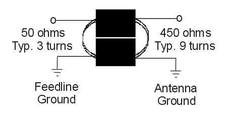
The sketch below describes most of the process, but I'll list the steps anyway:
1. Glue the two beads side-by-side into a single "binocular" core assembly
2. Wind a 3-turn primary through the core using the #22 AWG wire. A wire passing through both cores and back to the same end is one turn. Be careful to avoid scraping the insulation off the wire as you pull it through the core — the edges of the core can be rough.
3. Wind a 9-turn secondary in the same manner as the primary, using the #24 wire. It may be easiest to bend the wire in half — into a "hairpin" shape. Insert the two end through the cores for the first turn, then alternately wind each end of the wire until you have a total of nine turns.
4. When I'm finished, I apply a generous dab of Duco polystyrene glue to each end — to hold everything solidly together.
5. The result should look something like this:

FAQ and COMMENTS—
1. Why use two different wire sizes? Well, it's not really needed, but it sure makes it easy to identify the primary and secondary windings after the transformer is completed. I have also made these transformers using only #24 wire, but with two different colors of enamel.
2. Do I really need enameled wire? No, but when you nearly fill the hole in the core, and place the windings very close to one another, the efficiency (loss and accuracy) of the transformer is best. Enameled wire does this well, but I admit that enameled wire can be a bit of a nuisance to work with for inexperienced homebrewers. Good results can be had with Kynar-insulated "wire wrap" wire or other insulated wire that is small enough diameter to fit the required windings through the cores. It is also possible to make this transformer with larger wire, using 2 turns in the primary and 6 turns in the secondary. The resulting transformer will be quite acceptable for most hams, but the loss will increase somewhat.
3. Why 77 material, since it's harder to get than 73 material? Simple — it's the optimum material for the job! It has lower loss than the more common 73 material and a permeability that places the "sweet spot" of performance between 1 and 2 MHz. But go ahead and use 73 material if it's available to you — it will make a transformer with fine performance
4. How well does the transformer perform? This number of turns results in lowest loss in the frequency range of the 160M and 80M bands. Measured loss is 0.2 dB using the standard method of connecting two transformers back-to-back and dividing the result in half. Loss is 0.25 to 0.3 dB from the AM Broadcast band through the 20M ham band. With a 450 ohm resistor across the secondary, the primary will have a VSWR of 1.2 maximum from below the AM Broadcast band to 30 MHz. Note that neat and tidy winding results in the best performance, although more "casual" winding techniques will not add enough extra loss to make a practical difference! Unlike toroid core transformers, this type of transformer is very forgiving of the builder's technique.
5. What if I want to match to 75 ohm line? The winding ratio can be changed accordingly. A secondary (high impedance) winding of 7 or 8 turns will work well with 75 ohm coax feedline. However, if you just go ahead and use this transformer as-is with 75-ohm line, the extra loss due to mismatch is so low that you will never detect the difference anywhere but on the test bench.