by Gary Breed, K9AY
When we think of Beverage antennas, we automatically think of several acres of land and lots of wire! Low band aficionados begin their consideration of Beverages at one wavelength. Not all of us have 540 feet available for a 160-meter Beverage, so we need to try other options, which is why we hear so much about EWEs, K9AY loops, flags, pennants, slinkys, snakes, short vertical arrays and other small antennas.
I'd like to discuss another option that hasn't gotten as much attention - short Beverage antennas. Although I will use EZNEC 3.0 plots to show how these antennas work, this is not just a modeling exercise. I have used several different short Beverages and can testify to their usefulness. My experience also confirms that the computer-generated results are good representations of these antennas. Let's see how they work.
First, note that I will use the 160-meter band for all the antennas in this article. To apply the information to other bands, simply scale the lengths accordingly.
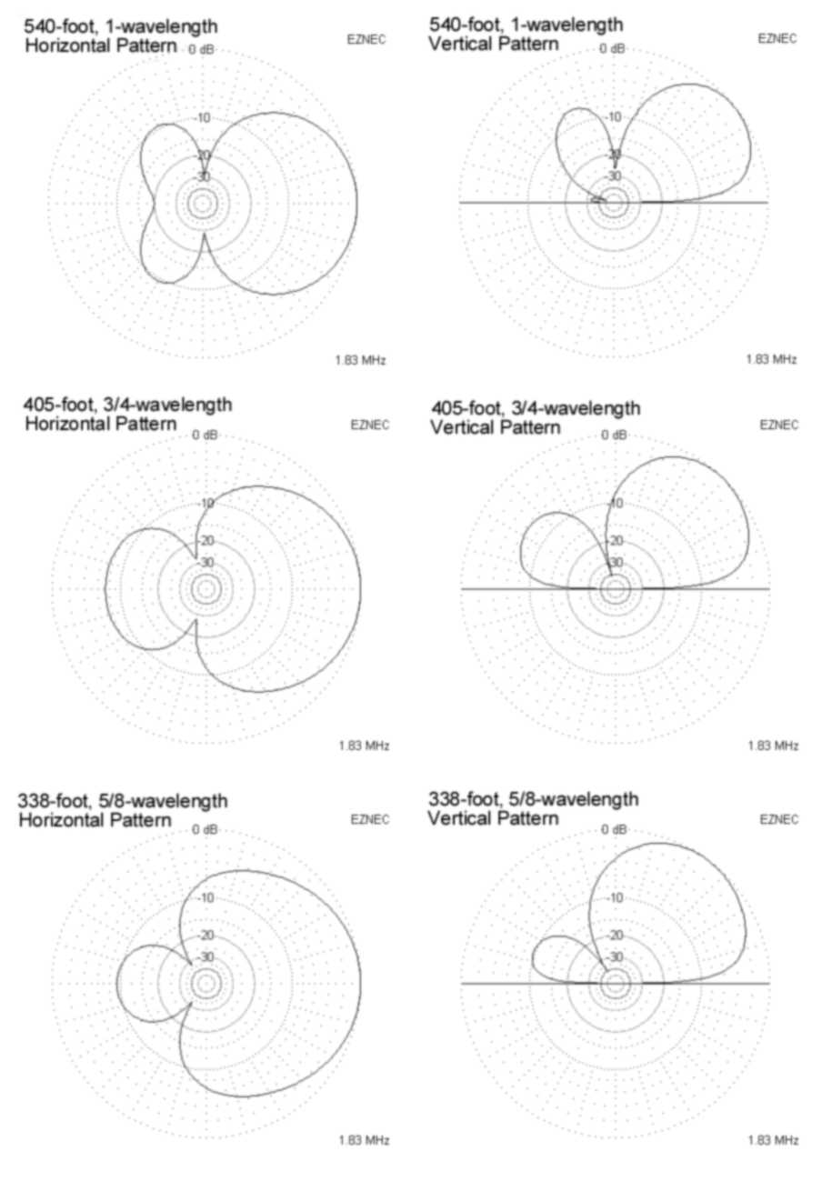
Figure 1 (below) is a sequence of pattern plots for six Beverages, starting with a 540-foot long one-wavelength antenna, followed by progressively shorter versions down to 135 feet, or 1/4-wavelength. For each length, I used a simple resistor termination, with the resistance value optimized for best front-to-back ratio. All azimuth plots are at 30 degree elevation angle. You can easily see from this series of plots that the patterns become less directive as the length deceases, although lengths as short as 270 feet (one-half wavelength) still have significant directivity. Once the length is reduced below 1/2-wavelength, directivity is hard to achieve in an ordinary Beverage configuration.
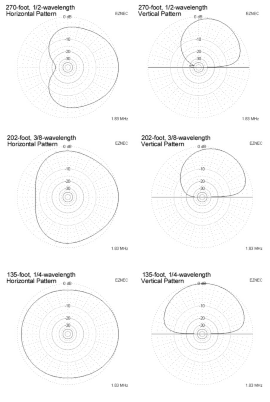
Figure 1. Radiation patterns of six different length Beverages from 1 wavelength down to 1/4-wavelength.
Although the 3/8-wavelength Beverage has some directivity, the shortest Beverage with a truly useful pattern is 1/2-wavelength long. It provides good front-to-back directivity, although its forward pattern is quite broad in both azimuth (horizontal plane) and elevation (vertical plane). At 160 meters, the best termination resistance is 330 ohms for EZNEC's "average" ground conductivity of 0.005 mS/m and dielectric constant of 13. Depending on your local ground conductivity and the quality of your grounding technique, the best performance may be achieved with a different resistor value, probably between 220 and 470 ohms.
Over the past few years, I have installed seasonal Beverages about 350 feet long, using 270 ohm terminating resistors. These Beverages have demonstrated directional characteristics very much like those shown in Figure 1 for the 338-foot, 5/8-wavelength Beverage. The most prominent feature in the pattern, the side nulls toward the rear of the pattern, are quite deep and were observed to be located at the expected azimuths relative to the antenna's orientation. My usual setup has one Beverage toward Europe at 45 degrees azimuth and another at 290 degrees to cover the Western U.S., with JA and VK also in the main lobe. With these orientations, each antenna has a null nearly in line with the main lobe of the other. This is quite handy, nulling the Northeast U.S. when listening to the West, and vice versa.
Can we go even shorter?
OK, we can see that conventional Beverage construction and termination methods will work with antennas a short as a half-wavelength. Can we go even shorter? If so, what do we need to do to improve the directivity? The short answer (pun intended) is reactive loading.
Let's see what we can do with a 135-foot (1/4-wavelength) Beverage. First, refresh your memory with the pattern in Figure 1. Now look at Figure 2. The square box at the center of the Beverage indicates a load, in this case, an inductor to alter the phase of the signal along the antenna. Figure 3 shows the patterns with a +j1200-ohm (106 uH) load. Although the front lobe is extremely broad, this antenna has a 10 dB null off the back and a pattern shape similar to the classic cardioid.
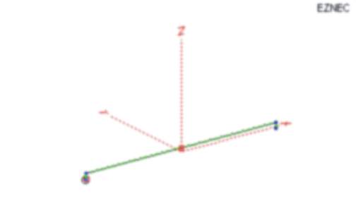
Figure 2. Diagram of a 1/4-wavelength Beverage with a loading inductor placed midway along its length.
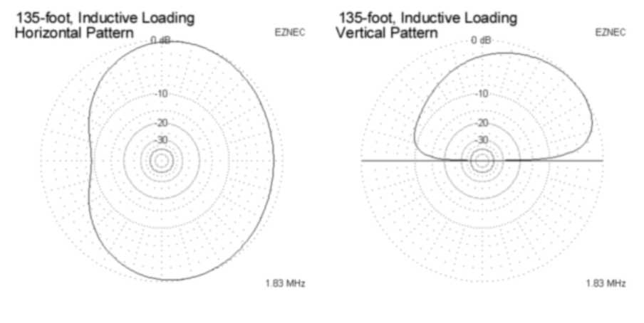
Figure 3. Elevation and azimuth
patterns of a 1/4-wavelength 160 meter band Beverage with a 106 uH loading inductor.
The loading can also be done with several inductors along the length of the antenna. Of course, the extreme version of this would be a single helical Beverage - the Slinky antenna. Be warned that it can be extremely difficult to calculate or experiment until you get just the right amount of loading using a Slinky. It's a lot easier to do this with one inductor.
I may be interesting to note that, with an ordinary terminating resistor of about 1200 ohms, this antenna (without the center coil) can become a long version of the EWE. In this case, its directivity is back toward the feedpoint, opposite that of a normal Beverage.
More complicated ideas
When a single antenna doesn't provide enough performance, we can combine them in various types of arrays. One way to narrow a broad forward lobe is to combine two Beverages in-phase in a broadside array with spacing of 1/2 to 5/8 wavelength (270 to 337 feet). Figure 4 shows the horizontal pattern of two 270-foot Beverages in a broadside configuration, spaced 270 feet apart. This is pretty good directional pattern! Four of these antennas can be arranged in a 270 x 270 foot square space and used two at a time. With relays to switch the feedlines and terminations, this system can cover four directions. If you need more coverage, two 380-foot Beverages will fit along the diagonals.Although this system is a lot smaller than a set of 500-foot or longer Beverages, it still occupies more than 1-1/2 acres!
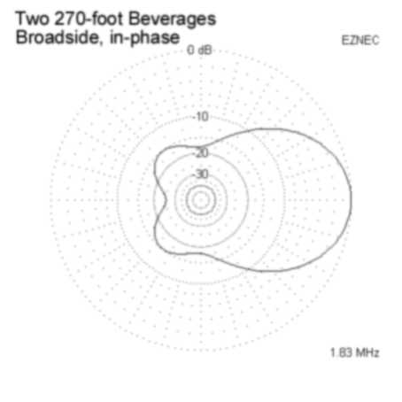
Figure 4. Horizontal pattern of a broadside array of two 270-foot Beverages, spaced 270 feet and fed in-phase.
Inline phased arrays can also be used, although they increase the overall length. Figure 5 is a horizontal pattern plot and pictorial diagram for two staggered 270-foot Beverages, spaced 20 feet apart horizontally and 70 feet along their length. The rear antenna is fed with a 135 degrees phase shift relative to the front antenna. If you compare this pattern with the single Beverage pattern in Figure 1, the improvement is obvious.
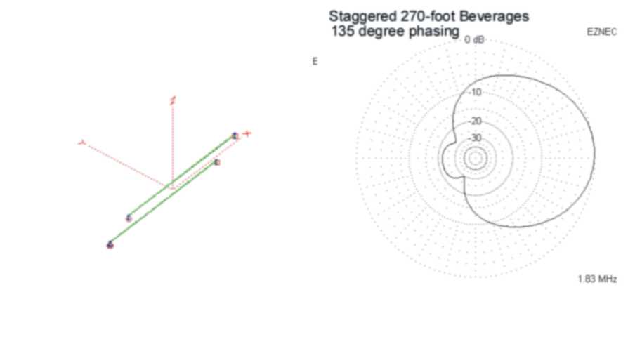
Figure 5. Antenna diagram and horizontal pattern of two 270-foot Beverages in a staggered configuration, fed with 135-degree phase difference.
What else can we do?
This article has only explored antennas in the form of traditional Beverages. It is possible to make antennas that are smaller than these, yet have much better directional patterns. Phased arrays of loops or short verticals can perform remarkably well. The highest performance arrays require phasing and switching systems that can be quite complex and intimidating, but the payoff in "performance per square foot" can be dramatic. I'll describe some of these high performance arrays in a future article.
Recommended reading
There are some excellent sources of additional information on this subject.
The Web site of Tom Rauch, W8JI (www.w8ji.com) has technical notes with information
similar to what I've described here, along with some additional small antenna
designs. Another good resource is Low Band DXing (Third Edition) by John
Devoldere, ON4UN, published by the American Radio Relay League (www.arrl.org).
There are also some good antenna discussions on the Topband reflector. Reflector
archives can be examined at www.contesting.com.